Sand Casting Structure
Sand Casting Design Tolerances
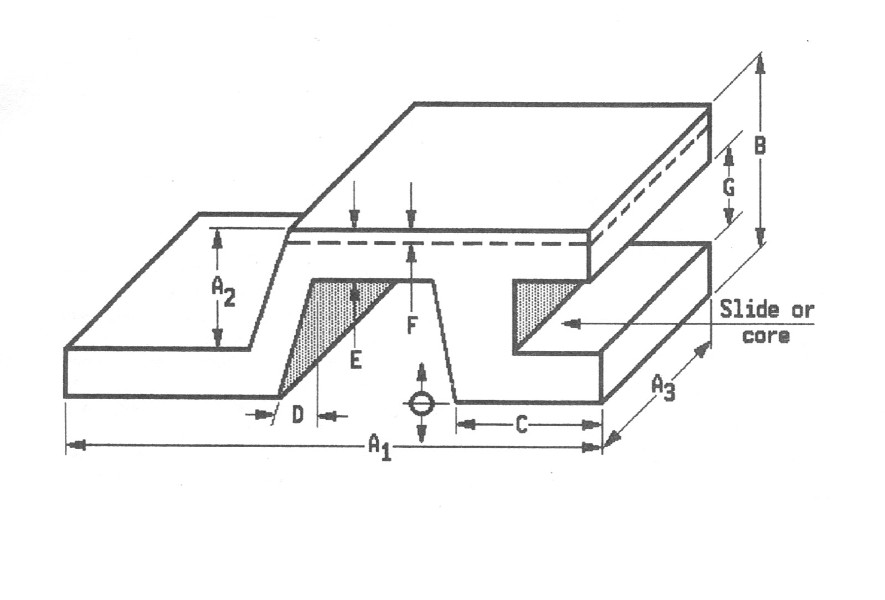
A) Between two points in same part of mold.
Up through 6”: +/- 0.030
Over 6”: 0.030 +/- 0.003 in./in. over 6”.
B) Across the parting plane. A-type dimension plus the following: Projected area of casting, A1 x A3 sq. in.
Additional tolerance for parting plane, inches.
- Up through 10: +/- 0.020
- Over 10 to 49: +/- 0.03
- Over 100 to 249: +/- 0.060
- Over 50 to 99: +/- .0045
- Over 250 to 500: +/- 0.060
C) Affected by moving parts. A-type dimension plus the following: projected area casting affected by core, A3 x G1 sq. in.
Additional tolerance for core, inches.
- Up through 10: /- 0.020
- Over 10 to 49: +/- 0.035
- Over 100 to 249: +/- 0.060
- Over 50 to 99: +/- .0045
- Over 250 to 500: +/- 0.060
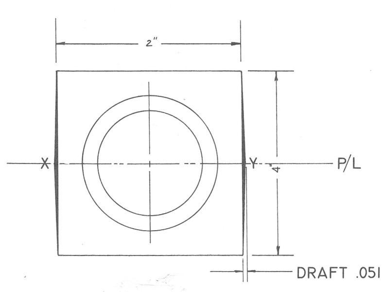
D) Draft, standard foundry practice is to “add” draft to the part. Each degree of draft will add .017” per inch of draw to dimension. Tolerances are measured plus or minus a given dimension plus draft. Minimum wall thickness for a sand casting is typically 0.150.
E) Shrinkage allowance: Aluminum @ 5/32” per foot, Aluminum Bronze @ 5/16” per foot and Brass & Bronze @ 3/16”-5/32” per foot depending on the alloy. Machine stock allowance varies per alloy and it is recommended consulting with the foundry engineer.
F) Weight conversion, per cubic inch for non-ferrous cast alloys- Aluminum @ .97-.101, Aluminum Bronze @ .274 and Brass & Bronze @ .310-.320. A cast iron manifold weighing 27 lbs. will weigh 10.4 pounds in aluminum, a total weight savings of 16.6 pounds if converted to an aluminum casting.
Click here to submit a Request for Quote
or call us today at 773-721-1186


